


 >


What to Pay Attention to When Machining Tungsten Carbide
By hqt
Oct 30, 2026
Related Posts

Stainless Steel Precision Parts: A Complete Guide to Stainless Steel Machining
2026-11-02<

What to Pay Attention to When Machining Tungsten Carbide
2026-10-30<

Stainless Steel Precision Parts: A Complete Guide for Modern Manufacturing
2026-10-27<

When Is a Hot Runner System Essential for Plastic Mold Manufacturing?
2026-10-22<
Tungsten carbide, commonly known in industry as cemented carbide, is a high-hardness alloy produced via powder metallurgy sintering, using tungsten carbide (WC) as the primary matrix and cobalt (Co) as the binder phase. Thanks to its exceptional wear resistance, red hardness, and reasonable toughness, tungsten carbide is widely used in manufacturing high-precision molds, cutting tool inserts, nozzles, seal rings, and critical components for semiconductor and medical applications. However, precisely because of its high hardness, high brittleness, and low thermal conductivity, machining tungsten carbide is far more challenging than working with ordinary steel. Improper process parameters can lead to rapid tool wear, edge chipping on the workpiece, or even cracking, dimensional deviation, and safety incidents. This article systematically covers the key points that must be addressed throughout the entire tungsten carbide machining process, helping operators improve yield and extend tool life.
1. Fully Understand the Machining Characteristics of Tungsten Carbide
Before starting any machining operation, operators must have a clear understanding of tungsten carbide's material properties. This is the foundation for developing a reasonable process plan.
First, its hardness is extremely high. General-grade tungsten carbide typically ranges between HRA 89–93, equivalent to over HRC 70, far exceeding high-speed steel and most mold steels. This means ordinary HSS tools cannot be used; tool materials with higher hardness and superior wear resistance are mandatory.
Second, tungsten carbide is brittle with relatively low transverse rupture strength. Compared with steel, tungsten carbide is prone to micro-cracks under impact loads or excessive clamping forces, and once a crack initiates, it cannot be repaired. Therefore, impact, vibration, and localized stress concentration must be minimized throughout machining.
Third, its thermal conductivity is low. The thermal conductivity of tungsten carbide is typically only one-third to one-half that of ordinary carbon steel. Heat generated during cutting cannot dissipate quickly through chips or the workpiece, and a large amount of heat concentrates in the cutting zone and on the cutting edge, easily causing tool thermal wear and surface thermal damage to the part.
Fourth, there are chemical affinity concerns. At high temperatures and pressures, tungsten and cobalt elements in tungsten carbide can diffuse and bond with certain tool materials (such as HSS and ordinary carbide), leading to rapid tool wear. Therefore, tool pairing must be carefully selected.
2. Reasonable Selection of Tool Material and Geometry
Cutting tools are one of the most critical factors in tungsten carbide machining. Choosing the wrong tool makes it impossible for even the most skilled operator to achieve satisfactory results.
In terms of tool material, polycrystalline diamond (PCD) tools or ultra-fine-grain carbide inserts should be the first choice. PCD tools offer extremely high hardness, excellent wear resistance, and good chemical stability, making them suitable for precision milling, turning, and drilling of tungsten carbide, and capable of delivering very low surface roughness. For roughing or interrupted-cutting scenarios where PCD may not be feasible, ultra-fine-grain carbide inserts with low cobalt content should be selected, preferably with TiAlN or AlCrN coatings to improve high-temperature oxidation resistance. It is worth noting that ordinary high-speed steel (HSS) tools and plain carbon steel tools can hardly machine tungsten carbide effectively and are not recommended.
Regarding tool geometry, the principle of "large rake angle, small relief angle, sharp cutting edge" should be followed. Because tungsten carbide is hard and brittle, the edge must remain sufficiently sharp to minimize cutting forces; at the same time, a small hone (typically 0.02–0.05 mm) should be applied to the edge to prevent chipping. The relief angle should not be too large, as this would weaken the edge; a value of 6°–8° is generally appropriate. The lead angle should be selected based on the rigidity of the process system: when rigidity is good, a smaller lead angle can increase the engaged edge length; when rigidity is poor, a larger lead angle should be used to reduce radial cutting force.
3. Scientific Setting of Cutting Parameters
Cutting parameters for tungsten carbide differ significantly from those for ordinary steel. The core principle is "low speed, small depth of cut, small feed rate."
Cutting speed is the most sensitive parameter. When machining tungsten carbide with PCD tools, cutting speed is typically controlled within 30–80 m/min; with ultra-fine-grain carbide tools, the speed generally does not exceed 20–40 m/min. If the cutting speed is too high, the temperature at the cutting edge rises sharply, tool wear accelerates exponentially, and thermal cracking of the insert may even occur.
In terms of depth of cut and feed rate, a roughing depth of 0.1–0.3 mm is recommended, while finishing depth should be controlled at 0.02–0.05 mm. The feed rate is generally 0.05–0.15 mm/rev for turning or 0.02–0.05 mm per tooth for milling. Excessive depth of cut or feed rate causes a sudden surge in cutting force, easily leading to edge chipping on the workpiece and insert fracture.
It should be emphasized that the "high-efficiency roughing" strategy of large depth and large feed is not suitable for tungsten carbide. Instead, a progressive machining approach with multiple passes and small allowances should be adopted. The cutting amount per pass should remain within the tolerable range of the tool and the process system. It is better to increase the number of passes than to attempt a single-pass finish.
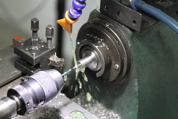
4. Cooling and Lubrication Strategy
Because tungsten carbide has poor thermal conductivity and cutting heat is concentrated, cooling and lubrication play an even more important role in tungsten carbide machining than in ordinary steel machining.
First, high-pressure, high-flow emulsion or minimum quantity lubrication (MQL) should be preferred. High-pressure coolant (5–10 MPa or higher) effectively breaks up chips, removes heat from the cutting zone, and prevents re-cutting of chips on the machined surface. For precision finishing, MQL can be used, where a very small amount of dedicated cutting oil is atomized and sprayed onto the cutting zone, providing friction-reducing lubrication without subjecting the workpiece to thermal stress cracks caused by sudden flooding.
Second, avoid suddenly flooding the tool with large amounts of coolant after it has already heated up. Tungsten carbide is brittle, and alternating hot and cold conditions can easily induce thermal cracks. The correct practice is to turn on the coolant before starting the cut so that the tool and workpiece remain in a stable temperature environment throughout the machining process.
Third, dedicated cutting fluids or oils should be used for tungsten carbide machining; their lubricity and extreme-pressure performance are superior to those of ordinary steel cutting fluids. Ordinary emulsions often cannot form an effective lubricating film under the high-pressure contact zone of tungsten carbide, which accelerates flank wear.
5. Process System Rigidity and Workholding
Tungsten carbide machining places extremely high demands on the rigidity of the entire process system. Any minute vibration is directly reflected in surface quality and tool life.
In terms of machine selection, machining centers or CNC lathes with good rigidity, high spindle accuracy, and excellent dynamic balance should be preferred. Older machines with excessive spindle runout are not suitable for precision tungsten carbide finishing. Tool holders should be high-rigidity, high-precision shrink-fit or hydraulic chucks, and tool overhang should be minimized. The longer the tool overhang, the poorer the rigidity and the more severe the vibration. Generally, tool overhang should be kept within 3–4 times the tool diameter.
For workholding, tungsten carbide parts cannot be clamped with excessive force as they would be with steel. Excessive clamping force introduces internal stress into the carbide workpiece and can even cause micro-cracks near the clamping point. Precision vises with narrow jaw openings or custom fixtures should be used, with evenly distributed clamping force, and copper or aluminum shims placed between the workpiece and jaws to protect the finished surfaces. For thin-walled tungsten carbide components, vacuum chucks or auxiliary supports should be considered to reduce machining deformation.
6. Safety and Quality Monitoring During Machining
Chips produced in tungsten carbide machining are fine and highly abrasive; flying chips can easily cause injury. Operators must wear safety goggles, transparent machine guarding must be installed, and the guard door must be closed before starting the spindle.
During machining, closely monitor chip formation. Under normal conditions, tungsten carbide chips should appear as fine powder or short segments. If chips become continuous ribbons, it indicates a problem with cutting parameters or tool geometry, and the machine should be stopped for inspection. Pay attention to the cutting sound as well: normal cutting produces a continuous, steady hissing sound. Intermittent thudding or high-pitched squealing usually indicates tool wear or chatter, and the edge must be inspected immediately.
Tool life management should also be institutionalized. Based on accumulated experience, a clear tool life limit (by number of parts machined or cutting time) should be set for each batch of tools. Even if the edge still looks acceptable, tools should be replaced once the life limit is reached, preventing excessive wear from causing part scrap.
7. Post-Machining Handling and Common Defect Countermeasures
After machining is complete, tungsten carbide parts should be allowed to cool fully before removal, to avoid thermal deformation caused by taking parts out while they are still hot. For precision components, stress relief treatment or natural aging is recommended after machining to stabilize dimensions.
Common defects in tungsten carbide machining fall into three main categories. Edge chipping and corner breakage are usually caused by a dull tool, excessive depth of cut, or improper entry strategy; they can be mitigated by keeping the tool sharp, reducing depth of cut, and using helical or ramping entry. Poor surface finish is typically related to tool wear, excessive cutting speed, or process system vibration; tool condition should be checked and parameters optimized. Workpiece cracking often stems from excessive clamping force, thermal shock, or inherent material defects; improvements should be made in workholding and coolant strategy.
Frequently Asked Questions (FAQ)
Q1: Can ordinary HSS tools machine tungsten carbide? A: Not recommended. The hardness of ordinary HSS is far below that of tungsten carbide, causing rapid tool wear within a very short cutting time. PCD tools or ultra-fine-grain coated carbide inserts should be used instead.
Q2: Why can't cutting speed be too high when machining tungsten carbide? A: Tungsten carbide has low thermal conductivity, so heat in the cutting zone cannot dissipate quickly. Excessive cutting speed causes the edge temperature to spike sharply, triggering accelerated thermal and diffusion wear and even thermal cracking, which drastically shortens tool life and degrades surface quality.
Q3: Is greater clamping force always better for holding tungsten carbide? A: No. Tungsten carbide is brittle; excessive clamping force introduces residual internal stress and can directly cause cracking. Moderate, evenly distributed clamping force should be used, with soft copper shims to protect the workpiece surface.
Q4: How to handle minor edge chipping after finishing tungsten carbide? A: Light chipping can be carefully polished with an oilstone or diamond lapping compound along the edge direction. For more significant chipping, address the root cause: replace the tool, reduce depth of cut and feed, optimize the entry path, and leave sufficient finishing stock before the final pass.


Request A Quote
We offer one-stop consulting services from design to mass production, ready to answer your questions anytime!


In This Article
Related Posts
Stainless Steel Precision Parts: A Complete Guide to Stainless Steel Machining
2026-11-02
What to Pay Attention to When Machining Tungsten Carbide
2026-10-30
Stainless Steel Precision Parts: A Complete Guide for Modern Manufacturing
2026-10-27
When Is a Hot Runner System Essential for Plastic Mold Manufacturing?
2026-10-22


